AutoCAD Tips & Tricks
Today's Tip
Mid Between 2 Points (m2p)
 Sometimes you might want to find a point midway between two other points. In the past, you might have drawn a line between these two points and then used "Snap to Midpoint" but this requires the drawing of a construction line and isn't very efficient.
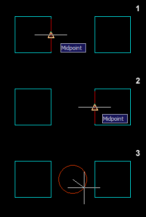
Enter the m2p object snap. This will find the midpoint between any two picked points without the need for a construction line.
How it works: Say you want to draw a circle midway between two squares, start the circle command and then enter "m2p" when prompted to specify the center point. Now just follow the prompts.
Command: circle
Specify center point for circle or [3P/2P/Ttr (tan tan
radius)]: m2p
First point of mid: (pick first point)
Second point of mid: (pick second point)
Specify radius of circle or [Diameter] <20.000>: (pick to complete circle)
Yesterday's Tip
Add additional "standard scales"

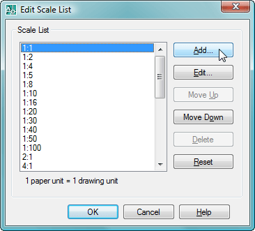
To create additional "standard scales" in AutoCAD, type SCALELISTEDIT. You will then see the Edit Scale List dialog, shown on the right.
Click on the Add… button. In the Add scale dialog, enter the name of the scale, for example "1:1250", this is the name that will appear in the list. Then enter the Paper units and Drawing units as desired.
Note: "Drawing units" refers to the modelspace units.
Thursday's Tip
Who is using that file?
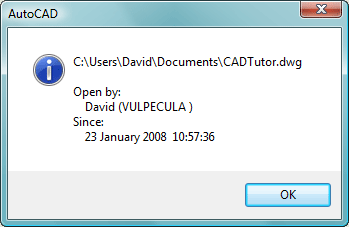
 If you are unable to open a drawing for editing (read-only) because it is in use, and want to find out who has it open, start a new drawing, or go to a drawing you have open and type WHOHAS at the command line. Browse to the drawing file using the file dialog box and double-click the filename (or select the file and click the Open button). A small message box will appear, showing who is using the file, the name of their PC and when it was opened.
Wednesday's Tip
Do you want to turn it into one? <Y>
When using PEDIT and selecting an object which is not a polyline you will get a message asking if you want to turn it into a polyline. This can be quite annoying if you're having to create closed polylines from a bunch of lines. To stop getting this message, type PEDITACCEPT and press Enter. Then type 1 and press Enter. This will automatically answer "yes" to the question in future.
Tuesday's Tip
Bring recent commands to the command line with the "Up" cursor key
Use the "Up" cursor (arrow) key on the keyboard to scroll through recently used commands on the command line. When you find the one you want, hit the Enter key to start that command.

You can also use the "Down" cursor key to scroll in the oposite direction.
Monday's Tip
Salvage a corrupted drawing
So, you opened a drawing only to find it has been corrupted. You've tried Recover but to no avail. Now what?
As a last resort, open a new drawing and then insert the corrupted drawing into the new one (). The insertion will only bring in the main (Model Space) components of the corrupted drawing; this trick does not recover any paper space objects. Hey, I didn't promise a miracle but it sure beats losing the drawing altogether now, doesn't it?.
Sunday's Tip
Repeat for Efficiency
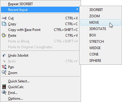
 Sometimes, you may find yourself having to use the same command repeatedly. This can be a pain, unless you are aware that the previous command can always be repeated by hitting the Enter key on the keyboard or by using the right-click mouse button and selecting the name of the command you just used. Both these methods are more efficient than repeatedly finding a command on a toolbar or from a pull-down menu.
What's more annoying than having to repeat a single command (and more common) is having to repeat a sequence of maybe two or three commands. Obviously, you can't use the "Enter to repeat" trick. However, the right-click menu has another option that can help in these situations. Below the name of the last command used, is a menu option that says . If you select this option, you will see a list of all the commands used in the current drawing session, with the most recently used at the top.
Using this method, you can repeat any sequence of commands without having to return to a toolbar or pull-down menu.
Note: This function is controlled by the INPUTHISTORYMODE variable.
Tutorials of the Moment
The most recently viewed tutorials
ISO Paper Sizes
|
Entering Survey Data using AutoCAD
|
|
Last visited: less than one minute ago |
Last visited: 1 minute ago |
|
All About Shadows
|
Project Overview
|
|
Last visited: 2 minutes ago |
Last visited: 3 minutes ago |
Local Navigation
Tutorials
Helping you to learn more of the skills you need, for free.
Featured Tutorial:
CADTutor tutorials are comprehensive lessons, designed to give you a deeper understanding.
Total tutorials: 108
Sponsored Links


