Reference and Obscured Variables
Receiving drawings from outside (or even from others within your own company) can be a wee bit aggravating sometimes. This month covers the Reference option in the Scale and Rotate commands that might give you a bit more leverage in your productivity. You'll also find out about a buried feature called BASE, that enables you to assign a basepoint to a drawing. And if you've always wondered if you can set up AutoCAD to 'see' the hidden lines in another format, AutoCAD 2002 has the answer. You may also pick up a trick in the Basics section where we cover text justification.
If you would like to contact me directly, you can do that also.
Blessings to one and all,
Michael
Scale & Rotate
References Provided Upon Request
There are two commands that have a Reference option but you have to know when and how to use it. In this section we'll take a look at the Scale and Rotate commands and where to use the Reference option.
SCALE / Reference - What if you get a drawing from the outside and it is not 1:1? The width of a door isn't 3'0" (or 900), but something squirrely like 4.975. Clearly not a metric factor nor a factor of 12. Give this a shot:
- After backing up the drawing, Thaw, turn On and Unlock all layers.
Note: You may want to consider saving the current Layer State (Save State in the Layer dialog) prior to doing this.
- Zoom into an area where you know the true distance between two points. This may be a door opening or some location that actually has a dimension shown (albeit incorrect).
- Launch the SCALE command and at the prompt to select objects, enter ALL.
- When prompted for the base point, enter 0,0. This is important if this drawing is externally referenced into another drawing.
- At the prompt to "Specify scale factor or [Reference]", enter R for the Reference option.
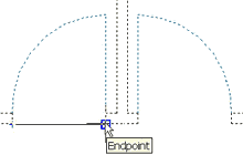
- At the prompt to "Specify reference length", enter the current incorrect distance or pick two points to define it (remember to use osnaps for accuracy!).
- At the prompt to "Specify new length", enter what you want that distance to be; in this case, 36.
- Zoom / Extents, then confirm the value specified.
ROTATE / Reference - Occasionally we inherit drawings from others in which the objects are not 'square'. Somehow the rotation of the objects got convoluted and we have to straighten them up.
- Zoom into the objects to be straightened and launch the Rotate command.
- Select the objects to be rotated and press Enter, then pick a base point at the "Specify base point" prompt. This point will effectively serve as the pivot point in the rotation of the objects.
- When prompted to "Specify rotation angle or [Reference]", enter R for the Reference option.
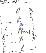
- Accurately (with object snaps), pick two points that graphically define the reference, or skewed, angle. In essence, you're identifying the angle you want to fix.
 |
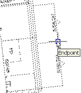 |
| Pick the first point of the skewed angle… | Pick the second point to define the skewed angle |
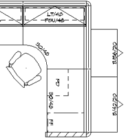 When prompted to "Specify the new angle", you can enter whatever you want that line to be. In the example on the right, I set the new angle to 0.
Power Tool
Obscured Variables
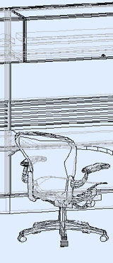
I was hunting for something in A2002 and stumbled on this. If you want to see the hidden lines of a 3D drawing, use the "Obscured" variables.
The Players…
OBSCUREDLTYPE
Available settings:
| OBSCUREDLTYPE settings | |
|---|---|
| 1 | Solid |
| 2 | Dashed |
| 3 | Dotted |
| 4 | Short Dash |
| 5 | Medium Dash |
| 6 | Long Dash |
| 7 | Double Short Dash |
| 8 | Double Medium Dash |
| 9 | Double Long Dash |
| 10 | Medium Long Dash |
| 11 | Sparse Dot |
OBSCUREDCOLOR
Enter the color number of your choice.
The Game…
It's pretty easy. Once you have a drawing with 3D objects (solids, optimally), simply enter the values for these obscure variables (literally) and run the Hide command.
The Odd Spot
Establish your drawing BASE
When using WBLOCK to save selected objects as a .dwg file, you have the opportunity to establish the base point by which that drawing will be "held" when inserting it into another drawing. When you insert a drawing file that was not created using Wblock, however, AutoCAD presumes the base point for that inserted file to be 0,0 by default. To specify a point other than 0,0 as the drawing's base point without using Wblock, type BASE at the Command line and pick a point to be used as the base point for the drawing when it's inserted.
The Basics
Text Justification
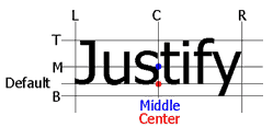 When you want to center Dtext in a circle, use one of the Justify options.
- Draw the circle in which you want to place the text, then begin the Dtext command.
- When prompted to "Specify start point of text or [Justify/Style]", enter J for the Justify option.
- You will be presented with several options…
[Align/Fit/Center/Middle/Right/TL/TC/TR/ML/MC/MR/BL/BC/BR]:
- Based upon the figure shown, to place text centered in a circle, you could either use Middle, Center, or MC.
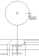
- After entering your selection, you are prompted to specify the middle point of the text. Use the "Snap to Center" object snap and pick the edge of the circle.
 |
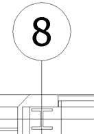 |
- Now enter the Height of the desired text (if prompted) and the rotation.
Note: If you were not prompted for a height, that means the height of the current text Style has been preset. You can edit the height of the text using the Properties window after entry if necessary.
- When prompted to "Enter text"… go ahead!
Donate to CADTutor
If you found this article useful, you might like to consider making a donation. All content on this site is provided free of charge and we hope to keep it that way. However, running a site like CADTutor does cost money and you can help to improve the service and to guarantee its future by donating a small amount. We guess that you probably wouldn't miss $5.00 but it would make all the difference to us.
Note from Michael: I want to thank all of my customers for continuing to retain my training services (some for over three decades!) and let you know your donations do not go to me personally, but to the ongoing maintenance of the CADTutor ship as a whole and to support the yeoman efforts of my friend and CADTutor captain, David Watson, to whom I am grateful for this monthly opportunity to share a few AutoCAD insights.
The Basics
- Dual Dimensions in a Dim…
- UCSICON Options
- "Best of" Basics: Irreg…
- Tool Palette Basics
- Original Dimension Value
- Possible Solutions to th…
- Avoid Using 'Standard' i…
- Shorten the Plot Scales…
- Update the Source File B…
- User Increment Angles fo…
- Drawing Information
- 'Sign Language'
- Rotate with the Copy Opt…
- Use the INSERT Osnap on…
- To or From the Current L…


