 Michael’s Corner #37
January 2006
Resolve to Learn Some New Stuff!
I have an idea. Those of you that would like me to send you an email each month as soon as my monthly column is posted, send your email address to me using the contact form and as soon as it goes up, I'll send you a link to Michael's Corner. Why? Because you all get busy and don't necessarily remember to run out and check when my column is posted. But one of the few things you DO check is your email. Just a thought to help you get faster quicker.
This year, if you have AutoCAD 2006, definitely resolve to learn more about the Customize User Interface, the CUI. Last month you were introduced to it when I showed you how to customize your F1 key. This month I show you how to make a new custom toolbar as well as how to make a custom button that you can also add to a tool palette. Very useful stuff.
This month is rounded out with a quick comment about the Find utility along with the first installment of what may turn into a series on layout viewports. The idea was prompted by a guy that admitted to ignoring layouts as long as possible, but now found himself in a position where he really had to face the music. Another situation may be those of you in school or just starting out in AutoCAD and trying to learn it yourself. I hope this month's Basics section will get you on your way to a clearer understanding of layout viewports. Ah, yes… and a Happy New Year to each and every one of you and yours!!
If you would like to contact me directly, you can do that also.
Blessings to one and all,
Michael
Making a Custom A2006 Toolbar
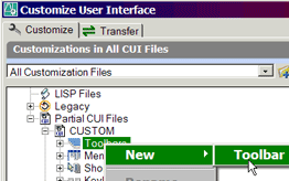 The AutoCAD 2006 CUI (Customize User Interface) replaces the A2000 - A2005 Customize dialog box and is very… shall we say… robust. You can easily find hundreds of CUI-specific pages on the Internet, but I'm just going to take you through the steps to make a custom toolbar and put one command on it. This month's Power Tool will take it one step further.
Instructions to Make a Custom Toolbar [A2006]
- To open the CUI, right-click on any toolbar, then go to the bottom and click CUI.
- Under Customizations In All CUI Files, expand Partial CUI Files, then expand CUSTOM. This will display the collection of customizable interface elements, including Toolbars.

- Enter a name for the toolbar, then press [ENTER].
- The lower left quadrant of the CUI displays the Command List. Scroll through those commands and find Distance.
Tip: You can click anywhere in the Command List, then type the first few letters of the command you're looking for.
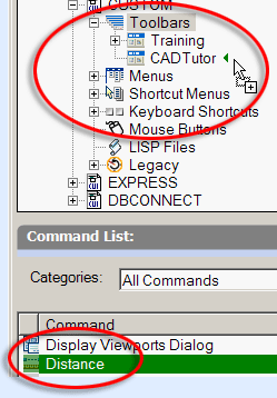
- Under the Command List, click on the Distance command, then drag it up and release it on your new toolbar.
- On the right side of the CUI, in the Properties area under Appearance, confirm that the value for On By Default is set to Show.
- Now click OK to apply and close the CUI. That's it!!

Tip: While you're in the CUI, in the listing of the commands on your custom toolbar, right-click on one of the commands for a shortcut menu enabling you to add a separator between the commands.
Blank Button on the A2006 Tool Palette
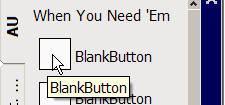 The Customize dialog box is now exclusively palette-specific; there's no tab for "Commands" as there was in A2005. So… here's a quick look at how to get a blank button onto a palette in AutoCAD 2006. Once you have one, you can copy it all you want after that.
What We Know About the A2006 Interface Features
- You can't drag anything out of the CUI [Customize User Interface].
- The CUI does not display palette information.
- The Customize dialog box in A2006 is for palette operations only.
- If the Customize dialog box is open, you can drag stuff between toolbars & palettes…
…Ergo/Therefore/So…
- You can drag a blank custom button from a toolbar onto a palette !
Instructions to Make a Custom Button
- Open the CUI. Under Command List, click New to create a new Command x in the list.
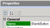
- Under Properties, enter a name (like BlankButton), then press [ENTER].
- Now drag BlankButton out of the Command List area and release it on the toolbar you created. This copies the button to the toolbar.
- Click OK to apply the additional button to the toolbar. Close the CUI. (The "smiley face" is no longer; now it's a mystery cloud. Fine, whatever.)
Instructions to Copy the Custom Button to the Tool Palette
- Open the Tool Palette, then right click on the title bar and click Customize to open the (now palette-specific) Customize dialog box. You can move the dialog box off someplace as you only need it to be open, not within reach.

- Drag the BlankButton tool from the toolbar onto the palette. Now you can close the Customize dialog box. You're Done!
Cool Things to Add to a BlankButton [A2005 & A2006]…
To add a macro to your blank button, right-click on the blank button on the tool palette, then choose Properties.
^C^COSMODE;8193 - A macro to set the OSNAP to Endpoint and Parallel.
^C^CUCS; OB ;\PLAN;; - A macro to set the UCS to the selected line.
^C^CLAYOUT;T;"Drive:/Path/Filename.dwt" - Select a Layout in the dialog box.
Note: If you are new to palettes, you may want to review my palette-related articles in March 2004, November 2004, December 2004, June 2005, and August 2005.
The Odd Spot
Find & Zoom To
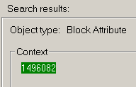
Some of your drawings are really complex. Objects and data everywhere. One of my customers in California has hundreds of numbered voice/data locations on their drawings. When they need to do some reconfiguring of the space plan, this comes in real handy when they need to find one of those locations.
Instructions to Locate Text in a Drawing
- From the menus, click Find >Replace to open the Find and Replace dialog box.
- Enter the text string to find, then click Find. If the text is in the drawing (even if that object's layer is Off, Frozen, or Locked!!), AutoCAD will find it.
- Now click the Zoom To button and AutoCAD will zoom to the first instance of that text string. If there are more objects containing that text string, click Find, then Zoom To for each instance.
Tip: If the text string is an attribute and the layer on which the text was created is Off or Frozen, you are not advised of the layer status. For all other text objects, you receive a notice regarding the visibility or locked status of the object's layer.
The Basics
Viewports in a Layout
 [Note: I'm just going to talk about viewports here, so to learn more about layouts, see The Basics, August 2005.] When you create a viewport in a layout, you are doing nothing more than cutting a hole in the "paper" through which you see the objects on the Model tab. In this procedure, you will need a drawing with some objects in Model Space so you can see them through the viewport you will create.
Instructions to Create a Layout Viewport
- Right-click on a layout tab and click New Layout to create Layout x, then click on that layout tab.
- If the Page Setup or Page Setup Manager dialog box opens, click OK to close them and go straight to the layout. If you already have a viewport, erase it … but don't panic.
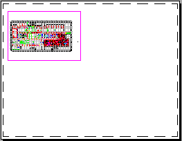
- Open the Viewports toolbar, a critically important element when working with layouts.
- On the Viewports toolbar, click Single Viewport which will create a rectangular viewport.
- Pick the two diagonal corners of the viewport such that the viewport is in the upper left quadrant of the layout. After picking the second corner of the viewport, AutoCAD will display the extents of the objects on the Model tab.
After creating the viewport you are still in the layout and anything you do will be done on the layout tab. You could add a rectangle as the sheet border, then add text. At this point you can also use the Move or Copy commands to move or copy the viewport to another location.
Instructions to Display the Viewport Objects to Scale
- To adjust the display of the Model Space objects in the viewport, double-click inside the viewport to switch to Model Space. To prove to yourself that you are only in that viewport, zoom or pan the drawing around with the commands or your wheel mouse. [When you want to return to the layout, double-click anywhere outside the viewport.]
- Use Zoom Extents to return your drawing to the full viewport display.
- On the Viewports toolbar, click the dropdown list to display the available predefined plot scales. If your drawing is architectural, scroll down and see what 1/8" = 1'-0" does. If you're working on a machine part, you may want to try 1:2 or 1:4. For those of you with a map, 1:100 may be a good starting point. If you don't see what you want, type in a ratio such as 1:500.
And that, my friends, is the short version of viewports in a layout. I'll share some more with you next month, but here are some parting suggestions.
Viewport Suggestions
- Since a viewport is created on the layer that's current when you click Single Viewport, give these a thought: Before creating your viewport, in the Layer Properties Manager, create a new layer named something like VPorts , make it Red, and set it to No Plot. Add that layer to your template.
- Remember when you're in the layout, you can only select the viewport frame, not the Model Space objects.
- You can have more than one viewport and each viewport can have it's own plot scale. Seriously.

- To freeze layers in only one viewport on the layout: If you have more than one viewport in a layout, double-click in the desired viewport, then in the Layers dropdown list, use the Freeze/Thaw in Current Viewport icon (the small sunshine with the box beside it). Cool, huh?
Left Field
From here to NYC When using your map software to find the distance from anywhere to NYC, the destination point is measured to the statue of Columbus in Columbus Circle at the SW corner of Central Park.
Donate to CADTutor
If you found this article useful, you might like to consider making a donation. All content on this site is provided free of charge and we hope to keep it that way. However, running a site like CADTutor does cost money and you can help to improve the service and to guarantee its future by donating a small amount. We guess that you probably wouldn't miss $5.00 but it would make all the difference to us.
Note from Michael: I want to thank all of my customers for continuing to retain my training services (some for over three decades!) and let you know your donations do not go to me personally, but to the ongoing maintenance of the CADTutor ship as a whole and to support the yeoman efforts of my friend and CADTutor captain, David Watson, to whom I am grateful for this monthly opportunity to share a few AutoCAD insights.
The Basics
- Dual Dimensions in a Dim…
- UCSICON Options
- "Best of" Basics: Irreg…
- Tool Palette Basics
- Original Dimension Value
- Possible Solutions to th…
- Avoid Using 'Standard' i…
- Shorten the Plot Scales…
- Update the Source File B…
- User Increment Angles fo…
- Drawing Information
- 'Sign Language'
- Rotate with the Copy Opt…
- Use the INSERT Osnap on…
- To or From the Current L…


