Summer at the Beach
This month's tips are like those special items you may find as you walk along the beach; not exactly part of your daily regimen and it depends on when you take your walk. My customers are driving these tips again, too. I did some training in Dallas for a US Defense contractor and decided to customize the training on the spot… and learned something along the way (which is always an added blessing to any training session).
Then after my NeoCon 2006 AutoCAD Toolbelt presentation, Lee Ambrosius came by to say hello and answered a question of one of the attendees; thank you Lee! [If you're looking for a good AutoCAD reference book, check out the book Lee recently co-authored when you get a chance: AutoCAD and AutoCAD LT All-in-One Desk Reference for Dummies]
And finally, the Basics this month covers a procedure I don't typically promote, and yet there are times when it can make sense. Specifically, dimensioning Model Space objects in Paper Space. That will make many of you cringe, but take a look and see if, for certain applications, it may not be a bad idea.
If you would like to contact me directly, you can do that also.
Blessings to one and all,
Michael
Dynamic Blocks: Visibility Parameter

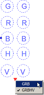
Dynamic blocks (A2006 / A2007) have many wonderful characteristics, among them is the ability to have a single block with multiple "visibility parameters". In other words, you can have a single block of a door in which you can display a variety of sizes. In my recent training, the customer did electronic diagrams requiring two different cabling configurations… GRB and GRBHV… so here's what we did:
Instructions to Create a Dynamic Block with Two Visibility Parameters
- Create the desired geometry, then launch the Block command.
- When selecting the objects for the block(s), select all the objects for the blocks. When you get to the Block Editor you will select the geometry to be displayed for each block.
- After specifying the Base Point and the name, be sure the box is checked for "Open in block editor ", then click OK.
Note: If you have not worked with Dynamic Blocks before, the Block Editor can be a bit disconcerting because your drawing appears to have disappeared with the exception of your block geometry. Don't Panic. The Block Editor is an entirely separate graphic environment in which you assign the dynamic features to your block.
- On the Parameters tab of the Block Authoring Palettes, click Visibility Parameter. When prompted to specify the parameter location, pick a point that will be easily seen for both of the block conditions. You will see the icon along with an exclamation point in a yellow box.

- In the upper right corner of the Block Editor, click Manage Visibility States to open the Visibility States dialog box. Click New and enter the name of one of the visibility states. Turn on the setting to "Leave visibility of existing objects in new state". Click OK. To name additional visibility states, click the New button as often as needed and name the states. In this exercise I made two, GRB and GRBHV. (You can delete the default VisibilityState0 name).

When you click OK to close the Visibility States dialog box, you will notice the yellow box with the exclamation point is removed, indicating a successful assignment of two or more visibility states.

- In the visibility state dropdown list, set GRB to be current, then click Make Invisible and select the objects that are not to be displayed in the GRB visibility state.
- In the visibility state dropdown list, set GRBHV to be current to see the other objects.
Note: You can move the position of the Visibility parameter icon at any time while you are in the Block Editor.
- Click Close Block Editor and save the changes. Click on the block to display the visibility parameter icon and select the desired visibility state!
Power Tool
Dynamic Plot Scale Text

Have you ever wanted the text stating the plot scale of the viewport to automatically change if you change the plot scale? Lee Ambrosius came by my training room after my NeoCon session in Chicago last month and offered the following solution to a question that came up after class.
Instructions to Assign a Plot Scale Field for Text
- In the Layout, enter the desired text indicating the scale of the viewport objects using Dtext (this will also work in Mtext, but I'm going to use Dtext in this example).
Note: In A2006/A2007, to get the previous editor to come up when you double-click Dtext, set the variable DTEXTED to <1>.
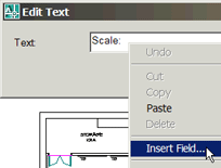
- Double-click the text to open the Edit Text dialog box, then right-click where you want to place the scale and click Insert Field.

- In the Field Names column, select Object. Above the middle column, click Select Object and select the viewport frame (this presumes that the layer on which the viewport was created is On).
- When the Field dialog box re-opens, in the Property list click Standard Scale and you will see the plot scale value of the viewport displayed in the Preview box at the top. Click OK to return to the Edit Text dialog box.

- Click OK to close the Edit Text dialog box, then press Enter to complete the command. If your system is set to display the background of the fields (per ) you will see a gray background for the plot scale text.
- To test this, double-click inside the viewport, change the plot scale, return to the Layout and Regen the drawing (or use the Regenall command to cover the bases without returning to Paper Space).
Now THAT'S pretty cool! That Object feature in the Field command is full of powerful stuff like that. Take a look at my August 2005 for another application for Object properties.
The Odd Spot
Don't like the new combined Xref dialog?

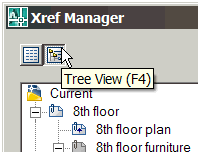
Yes, AutoCAD 2007 has combined the Xref dialog box and the Image dialog box and turned them into an All-In-One palette called External Reference. Whatever. My customer, however, had some "issues" that were unable to be resolved in the new Xref palette. After taking a look in some Forums (not unlike our CADTutor Forum!), she found two commands you may find useful as well: Classicxref and Classicimage.
The Basics
Dimensioning Model Space Objects in Paper Space
Disclaimer: This is something you want to consider only after mastering dimensioning in Model Space. That said, before you begin, there are a few pre-requisites:

- Make sure the variable DIMASSOC is set to <2>.
- I would suggest you create a separate dimension style (named appropriately) for dimensioning in Paper Space in which the setting on the Fit tab is set to Scale Dimensions To Layout (Dimscale = 0 for you Dimvar junkies).
- You can do all the dimensioning on one layer, so set that one to current.
- In order to follow along, you need to have a drawing open with objects in model space and a layout tab with at least two viewports with each viewport set to a different plot scale. If that procedure is unfamiliar, take a look at the Basic section in January, 2006, Viewports in a Layout.
Given the above, here's how it works:
Instructions to Add Dimensions in Paper Space to Model Space Objects

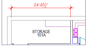
- In the Layout, launch the Linear Dimension routine and pick two points on the objects in Model Space in one of the viewports and place the dimension. The first illustration plot scale is 1/4" = 1'-0".
- Launch the Linear Dimension routine again, and for the other viewport, create another dimension in the Layout. If your viewports are two different plot scales (as mine are), you will notice that the dimension elements are the same size… and accurate!
So here are the questions opponents to this method bring up:

What if you move the viewport?
Answer: Use the DIMREGEN command. Try it.
Next question, what if I Pan the objects in the viewport?
Answer: Use the DIMREGEN command. No, really; try it. And believe it or not, that command even works if you change the plot scale in the viewport!
So out of the boodles of people reading this, there's a possibility that someone got, shall we say, "unexpected results".
Answer: Use the DIMREASSOC command and follow the prompts.
The benefit to this procedure is more evident for those of you who are working with 3D solids in Model Space and you have three views in a Layout. If you were dimensioning the model in Model Space, you would have to reorient the UCS and make sure it was in the right place in relation to the solid and it would be quite the tedious affair. By dimensioning the solid views in the Layout, you can more quickly accomplish your goal.
Follow-Up to June's "Unrecognized Fonts"
Solution from a reader in Houston, TX, USA
Michael, here is another solution regarding your topic "Unrecognized Fonts". This is a 'bigfont' solution, not a shape solution.
- Identify the style name that is not recognized. Upon opening the drawing in question, the "Select Font for Style…" dialog box will appear.
- Hit "Cancel" to exit "Select Font for Style…" dialog box and continue opening drawing.
- Go to "Style" command
- Highlight style name in step 1
- Uncheck "Use Big Font" box
- "Apply" and close
- Save and reopen drawing
Left Field
Real chocolate "coins": The Aztec Indians used the cocoa bean as currency. (As far as Godiva Chocolates are concerned… it still is!)
Donate to CADTutor
If you found this article useful, you might like to consider making a donation. All content on this site is provided free of charge and we hope to keep it that way. However, running a site like CADTutor does cost money and you can help to improve the service and to guarantee its future by donating a small amount. We guess that you probably wouldn't miss $5.00 but it would make all the difference to us.
Note from Michael: I want to thank all of my customers for continuing to retain my training services (some for over three decades!) and let you know your donations do not go to me personally, but to the ongoing maintenance of the CADTutor ship as a whole and to support the yeoman efforts of my friend and CADTutor captain, David Watson, to whom I am grateful for this monthly opportunity to share a few AutoCAD insights.
The Basics
- Dual Dimensions in a Dim…
- UCSICON Options
- "Best of" Basics: Irreg…
- Tool Palette Basics
- Original Dimension Value
- Possible Solutions to th…
- Avoid Using 'Standard' i…
- Shorten the Plot Scales…
- Update the Source File B…
- User Increment Angles fo…
- Drawing Information
- 'Sign Language'
- Rotate with the Copy Opt…
- Use the INSERT Osnap on…
- To or From the Current L…


