 Michael’s Corner #126
June 2013
The Big Three: Layers, Text, & Blocks
When you boil down a drawing—(so, what would that be? Alphabet soup?)—the key ingredients are Layers, Annotation, and Blocks. To communicate effectively, every drawing must have some component of each of those. You could probably go without having blocks, but what drawing doesn't contain blocks these days? This month, I touch on each of those.
…Merge Layers is a new arrival in AutoCAD 2014
…Another trick for the Single Line text devotees: Symbols ala Mtext
…An Mtext setting that will make you want to use Single Line text (until you figure it out)
…Clarification of what the Wblock command can do for you
This month I return to NeoCon with my Revit for Dealership Designers [Monday, 6/11, 4:00] in the official NeoCon seminar listing, and I'll also be presenting an off-site AutoCAD Toolbelt seminar [Tuesday, 6/12, 2:30], graciously hosted at the Kimball showroom across from the Merchandise Mart in downtown Chicago (my favorite U.S. destination).
Looks to be a great month ahead. Hope yours is, too!
If you would like to contact me directly, you can do that also.
Blessings to one and all,
Michael
Merge Layers in AutoCAD 2014
My contract furniture customers frequently receive building shells for tenant spaces. In an effort to cut down on the number of layers—especially if the architectural space in the scope of work is complete—my customers over the last couple weeks have found the newly-introduced Merge Layers feature to be a great tool.
Sidebar: For those of you who think you have seen something like this before, you have. There is a similar capability in the Layer Translator found on the Manage tab [see Michael's Corner, May 2008, or p. 40 in The AutoCAD Workbench, 2nd Edition].
How to Merge Layers
 Launch the Layer Properties Manager.
Select the layer(s) to be merged to another layer.
Note: Use CTRL to select more than one layer. To select a range of layers, select the first one, then hold down Shift and select the last one.
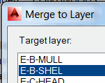 After selecting the layers, right-click, then click Merge Selected Layer(s) to…
In the Merge to Layer dialog box, select the target layer.
You will get a message to confirm your action; click Yes to continue.
The selected layers are purged from the drawing since they no longer have any objects on them.
Insights
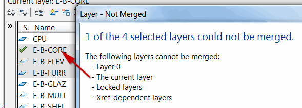
In certain situations, a dialog box will display regarding the current layer condition which is preventing the translation (shown here).
The geometry of a block that was created on a layer that was merged will be merged to the target layer (and will change color if different).
This can also be very effective in getting rid of unwanted layers or layers found to have nothing on them, but still won't purge out of the drawing. Simply select them and merge them onto another layer.
Power Tool
Hexadecimal Code in Dtext
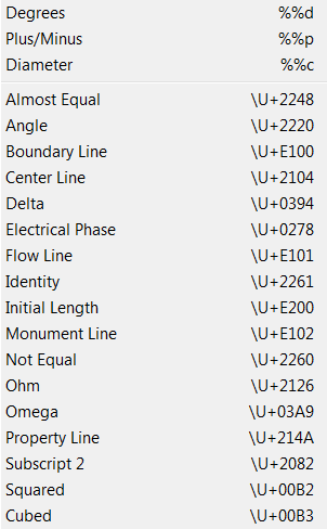 The AutoCAD users at Gerdau Ameristeel in Knoxville, TN kept me on my toes a couple months ago. One of the cool text features we came across was the way to put symbol characters—found in the shortcut menu of the Mtext editor—into Single Line Text. It's rather obvious, but it didn't occur to me until those guys asked about it.
To see the list of available Symbols, launch Mtext, then right-click in the Editor and hover on Symbol to display the list of available symbols that can be added to Mtext.
How to Add the Center Line Symbol to Dtext
Set your desired Layer and Text Style to be current.
Launch Single Line Text.
Specify your start point, Height, and Rotation.
Enter \U+2014, then press [Enter] twice to complete the text entry… and you see the Centerline symbol!


The Odd Spot
AutoCAPS in Mtext
 My buddy, Ben Senior, passed this one along to me, and it truly is a curiosity. Most conditions that are set from a shortcut menu or from a dialog box have an equivalent variable; not always, but there are a rare few which don't… and this is one of them.
Right-click in the Mtext editor, then turn on AutoCAPS. Even if your CAPS LOCK is off, you still get capitalized letters.
Even more disturbing, this setting is saved in the Registry. That means AutoCAPS will be the condition in all future drawings until such time as you turn off that setting. So now ya know.
The Basics
Block to .DWG with Wblock
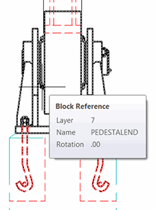 When collaborating with others, their drawing may have a block that you would like to use in future drawings.
One approach would be to add the block to a tool palette, but in the case of my friends at Gerdau Ameristeel, they needed to make adjustments to some of the machine part blocks for US compliance.
Solution: Wblock.
Briefly, the Wblock command [Write Block] has a dual purpose. The most common use of Wblock is to create a .DWG from selected entities in the current drawing, (see Michael's Corner, June 2006, or p. 103 in The AutoCAD Workbench, 2nd Edition).
The other use for Wblock is to create a .DWG from an existing block in the current drawing. This is where they got the term "write block"; you are writing a block definition to the disk as a .DWG file.
How to Create a .DWG from a Block
First, to optimize the application, click on the block in the drawing that you want to turn into a .DWG. This is the trick I learned from the guys at Gerdau.
Launch the Wblock command by typing W to open the Write Block dialog box. Notice that the name of the selected block is already in the dropdown list at the top of the dialog box.
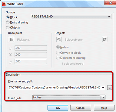
Under Destination, click the ellipsis (browse dots), to open the Browse for Drawing File dialog box.
Navigate to the desired folder, enter a name for the resulting drawing, then click Save. You will be returned to the Write Block dialog box.
Confirm the desired Insert Units, then click OK. You will see a very brief flash of a small window in the upper left corner of your screen as the .DWG is being saved.
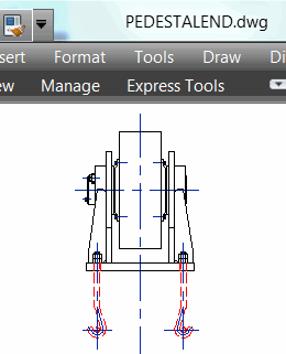 You now have a physical .DWG that consists uniquely of the geometry of the block in the source drawing.
Note: Any block geometry that was on a layer that was frozen when the Wblock command was used—such as the blue Centerline layer shown here—will still be present in the final .DWG since it was originally part of the block when it was created. Just because the layer was frozen didn't make it any less a part of the block definition.
Left Field
Worth Their Salt:
To be "worth one's salt" is to be worth one's pay. Our word salary derives from the Latin salarium, (sal is the Latin word for salt). There is some debate over the origin of the word salarium, but most scholars accept that it was the money allowed to Roman soldiers for the purchase of salt. Roman soldiers weren't actually paid in salt, as some suggest. They were obliged to buy their own food, weapons etc. and had the cost of these deducted from their wages in advance. From www.phrases.org.uk.
And then there's Lot's wife…
Find more fun salt facts at Morton Salt.
Donate to CADTutor
If you found this article useful, you might like to consider making a donation. All content on this site is provided free of charge and we hope to keep it that way. However, running a site like CADTutor does cost money and you can help to improve the service and to guarantee its future by donating a small amount. We guess that you probably wouldn't miss $5.00 but it would make all the difference to us.
Note from Michael: I want to thank all of my customers for continuing to retain my training services (some for over three decades!) and let you know your donations do not go to me personally, but to the ongoing maintenance of the CADTutor ship as a whole and to support the yeoman efforts of my friend and CADTutor captain, David Watson, to whom I am grateful for this monthly opportunity to share a few AutoCAD insights.
The Basics
- Dual Dimensions in a Dim…
- UCSICON Options
- "Best of" Basics: Irreg…
- Tool Palette Basics
- Original Dimension Value
- Possible Solutions to th…
- Avoid Using 'Standard' i…
- Shorten the Plot Scales…
- Update the Source File B…
- User Increment Angles fo…
- Drawing Information
- 'Sign Language'
- Rotate with the Copy Opt…
- Use the INSERT Osnap on…
- To or From the Current L…


